The supports of this series are designed for lighting any objects with the installation of brackets with a large number of lamps, for hanging SIP wires and installing advertising and other structures. The supports meet the strength requirements when exposed to normalized lateral static load.
Characteristics:
- The support has an inspection hatch with a strip for installing electrical components;
- Special reinforcement of the hatch ensures rigidity and strength of the structure;
- The support provides both underground and overhead power supply;
- It is possible to have additional hatches and holes (upon individual order);
- Product quality control is carried out at all stages of production;
- Climatic regions - II4...II11 according to GOST 16350;
- Windy areas - from I to VII according to SP 20.13330.2016;
- The external environment is slightly aggressive (in terms of the degree of aggressive impact) according to SNiP 2.03.11. The use of supports under other conditions is possible if there is a design justification and by agreement with the manufacturer.
To select and calculate the cost of supports, you must fill out the technical specifications
Advantages
- The material used is high-quality sheet metal from leading Russian manufacturers. The material is selected depending on the climatic area of operation according to SP 16.13330.2011, taking into account the safety factor.
- The anti-corrosion coating is applied by hot-dip galvanizing in full compliance with GOST 9.307, which ensures the safety of the product for 25-30 years of operation.
- The design is lightweight, making it easier to deliver and install the supports.
- There is a canopy above the inspection window, which ensures safe maintenance of the support in rainy weather.
- Additionally, at the Customer's request, products can be coated with a decorative paint coating according to the RAL palette.
- The supports of this series have increased load-bearing capacity and allow the installation of brackets with up to four lamps and a reach of up to 2.5 m.
Correspondence:
- Certificate of conformity TR TS 014/2011. Metal stationary supports
- GOST 32947-2014 «Public roads. Supports for stationary electric lighting. Technical requirements.»
- STO 07525912-340-2022 «Steel contact network supports for urban electrified transport.»
- Certificate of conformity STO 07525912-340-2022
- Compliance of zinc coating with GOST 9.307 «Unified protection against corrosion and aging. Hot zinc coatings. General requirements and control methods.»
Installation of catenary supports (h3)

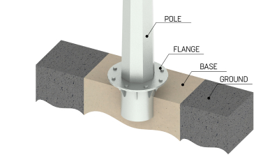
The installation of supports is carried out on reinforced concrete foundations containing a embedded element. The embedded elements for this type of supports are made of pipe (ZF) or anchor (ZA, on request) and are supplied separately. The main parameters of the foundation are determined based on the climatic conditions of the operating area and soil parameters using calculations.
Installation using the flange method is carried out by attaching the support with studs or bolts to the foundation element, which is pre-concreted in the ground.
This installation of overhead line support poles allows carefully dismantle the support for subsequent installation in another location.
Equipment installation
Brackets with lamps are installed on the support as standard. When installing brackets for more than 4 lamps and other equipment, coordination with the manufacturer and competent engineering calculations are required.
When supplying power cables underground (through windows in the embedded element), inspection hatches with component installation strips and a grounding point (M10 bolt) are provided.
When supplying air power, the grounding point is located at a distance of 900–1000 mm below the upper edge of the support.
Utility poles are selected in height based on the requirements for withstanding lateral loads. The lateral load is determined when designing an overhead line performed by self-supporting insulated wires and is calculated depending on the type and number of suspended wires, purpose (intermediate, anchor, corner, end) and climatic operating conditions.
The use of supports for operation in windy areas with a coefficient of V and higher, climatic zones I4-II3 must be justified by the design and agreed with the manufacturer.
Since supports and suitable equipment for them are complex technical products, the parameters of which significantly depend on operating conditions, type and placement of the load on the crown, each type of support requires filling out a technical specification.
Fill out the checklist, and our specialists will calculate the required product parameters according to your technical specifications.